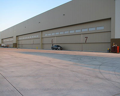
Vertical Lifting Hangar Doors

Vertical Lift
Flexibility
Our vertical lift hangar door systems are available in many configurations to meet your specific requirements. Having built vertical lift door systems over 30' tall and over 130 feet in width, with wind loads (while closed) up to 200mph, we are confident that we can build a system that will meet your requirements or your imagination.
Design
Doors are designed using CAD and structural engineering software. Door frame structure and connection designs are certified by an independent engineer. Door frames are engineered using structural steel and cold formed members per AISC and AISI codes. Wind loads are calculated using your location and building size for the most accurate structural loading possible. We don't make an assumption on the wind load by using an arbitrary standard, we check every time.
Construction
Door components are manufactured to the highest standards and designed to be completely bolt together, avoiding costly delays due to welding inspections and the availability of certified welders in the field. Door components are also designed to have as few connections as possible, simplifying and increasing assembly speed on the job. This lowers the total installed cost for your door system.
Lift System
There are three systems available for lifting. The premiere design we use for lifting doors is the hydraulic lifting unit. By utilizing a hydraulic cylinder to control door movement a large safety factor is gained. Hydraulic fail safe valves are used to lock the cylinder in place if a control valve should fail or a hydraulic line is ruptured or damaged. (We became real believers in this system and the components we use after another company's careless employee ran a piece of equipment into the hydraulic lines of a large canopy door while the door was open and construction personnel were working directly underneath it. Other than some hydraulic oil that spilled out of the broken pipe there was no further damage to the door system and more importantly the door didn't fall. So no one got hurt, or worse. This particular door weighs over 14,000 lbs. After settling about 1", which is the fluid volume necessary to activate the fail safe valve, the door maintained its position for over a week before we were contacted and repairs could be made). The closing speed can be easily tuned by adjusting the factory installed speed control valve. The lifting winch system offers simplicity in design and installation. The lifting winches are directly mounted to the door frame, so no lift unit is necessary. No pulleys need to be added to the building and no compressive force is exerted on the header. All this adds up to very few moving parts, which equates to lower maintenance costs over the life of the door. The third lift system available is the tried and true counterweight system. The counterweight system has been used on countless doors for as long as doors have been built. The main drawback with this system is the space required for the counterweight tower and the cost of the counterweight material.
Supporting Cables
Vertical Lift doors are supported by galvanized cables using a safety factor of at least 5-1, stainless steel cables available upon request.
Fall Restraint Safety System
We install our fall restraint safety system on every vertical lift door we manufacture. This system uses a spring loaded pin to arrest door movement if the lifting cable(s) lose tension. The pins are rated for 1.5 times the weight of the door panel to account for the increased energy of the door panel as it begins to fall. The maximum amount the door can fall under complete lifting cable failure is 12". This spacing can be reduced if required, 12" from support block to support block is standard. This design was submitted and approved by the Army Corp of Engineers for use on a large vertical lift doors we built for the U.S. Air Force. A demonstration video was made at our facility with the engineers present while we disconnected the lifting cables on our vertical lift door in the rear of our shop.
Door Supporting System
The cables are supported by solid steel pulleys that are machined in house and installed with roller bearings for a long service life. Pulley axles are drilled and tapped for grease fittings for ease of maintenance.
Weatherstrip
Weatherstrip is 1/8" cloth inserted epdm. Weatherstrip meets military specifications for durometer, UV resistance and incidental exposure to paint thinners. Retainer bar is fastened by zinc coated self drilling screws every 8" for a secure seal without oil canning of retainer bar. Retainer bar is easily removed for replacement of weatherstripping if it becomes necessary. Leading edge bubble seals allows for 4" of compression.
Electrical Controls
Door control panels are manufactured in house using only the highest quality UL listed components. Door control systems utilize electromechanical relays that are highly resistant to electrical interference and have no programming that can become corrupted requiring service. Door control systems also utilize solid state proximity sensors for limiting door travel. These sensors are water proof and have no moving parts to wear out. Door control systems can be supplied ranging from 12VDC to 600VAC. Variable frequency drives are available for custom tuning or varying of door operating speed. Variable frequency drives come with variable speed buttons with 3 adjustable speed settings standard, 5 speeds as an option.
Standard options
Timer delay with safety noisemaker and/or strobe light, safety edge with delay and/or auto reverse, personnel door frames and safety interlock sensors, explosion proof drive system, air drive operating system, hydraulic drive operating system, 12VDC backup hydraulic pump system, engine driven backup hydraulic pump system. Door drive motors and control panels are fully assembled, wired and tested at our facility prior to shipping.
